| |
|
 |
| |
|
 |
 |
|
 Drive
Assembly Drive
Assembly
Located within the Red Zone, the Drive Assembly
is responsible for supplying drive from
the Motors to the wheels. The Drive Assembly is a series of gears
and linkages located within the chassis. Stresses introduced
through
the gear
train
are dispersed through the chassis avoiding exploding gears and
the dreaded ‘clicking’ of slipping gears. While extended
gear trains tend to introduces ‘flex’ and ‘slop’ the
relative compact volume of the red zone allows for tight
and complex gearing configurations to be built.
When considering what type of Drive
Assembly to build we need to conceder the following 2 questions
|
 |
|
What steering
implementation we want to use? |
 |
|
How fast and
responsive do we want our Rover to be?
|
| |
|
|
| |
|
Steering
Implementation
- Exclusive vs. Differential
While we will cover steering method on the next page, the
configuration of the Drive Assembly allows for two fundamentally
different steering
implemetations of the same steering method.
Typically we need two motors for controlled movement. In controlling
our Rover we want to be able to move forward, reverse, left and
right. Ideally we also need to keep track of wheel revolutions
for distance, and orientation calculations. We can implement this
in two ways
|
| |
|
|
| |
|
Exclusive Drive
Gearing
The simplest form of drive control is to have a single motor independently
connected to each wheel. When both motors are moving forward – The
Rover moves forward. When the motors operate in opposite directions
the Rover turns. Gearing relationships
within the drive train determine speed and accuracy of these movements.
 This
type of Steering is often implemented on tracked or heavy vehicles (such
as earth moving, construction and military vehicles) and
is commonly referred to as ‘Skid Steering’. When
the vehicle turns, one side ‘skids’ while
the other moves. Many real life Rovers, Robots and human operated
machines
use this steering method. While not very elegant, it is an extremely
simple concept which is easy to implement and control. This
type of Steering is often implemented on tracked or heavy vehicles (such
as earth moving, construction and military vehicles) and
is commonly referred to as ‘Skid Steering’. When
the vehicle turns, one side ‘skids’ while
the other moves. Many real life Rovers, Robots and human operated
machines
use this steering method. While not very elegant, it is an extremely
simple concept which is easy to implement and control.
|
| |
|
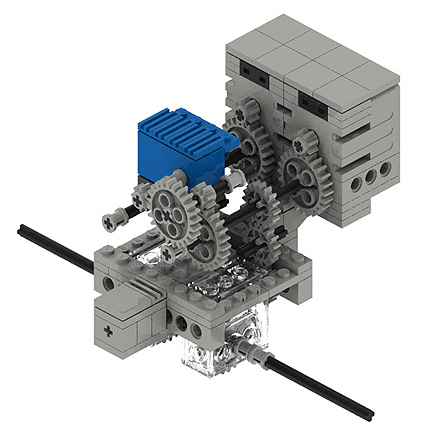 |
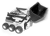
| ‘Skid Steer’ Drive
Assembly for the M.O.P Chassis. Independent motors drive each
wheel with an Angle sensor
mounted on a single drive axel to monitor rotations.
|
| |
|
| |
|
The main disadvantage
of this type of drive and control implementation in LEGO is that
not all motors are the same. Each motor turns at a slightly different
rate depending on wear, loading, and available power). Any variation
between the two drive motors results in the Rover changing orientation.
Accumulative error compounds this occurrence and in prolonged operation
the Rover can become horribly disorientated. Methods to compensate
this involve mechanically linking motors, Rigging up rotation sensors
around drive shafts to measure axle revolutions, and fancy control
software to constantly monitor motor output – All somewhat
compromising the simplicity of the initial idea.
It must be noted that in real life we are able to control actuators
a lot more accurately than we are able to do so with LEGO motors,
but non the less varying motor performance is an issue.
|
| |
|
 |
| |
|
|
| |
|
Differential
Drive Gearing
Are there any alternatives to independently driving each wheel? How
do we get around varying motor performance? Well lucky for us the
problem is not that great if we change the relationships between
the motors and wheels.
In the Skid Steer example mentioned previously, the output of
the two drive motors were independent, or exclusive of each other
(Motor output 1 has no effect on Motor output 2). If we change
this relationship to being inclusive (both motor outputs linked)
we get a much more usable product. Motors linked via an ‘differential’ gear
linkage can implement ‘skid steering’ with much more
control and reliability.
What this means in practical terms is that rather than have
one motor drive one wheel independently of the other (forward
/ reverse movement is achieved by both motors running in parallel)
, we use one motor to drive both wheels to produce forward or
reverse movement, and the other motor drive both wheels to produce
left / right movement. (Motors can be thought of as acting in
series with each other)
|
| |
|
 |
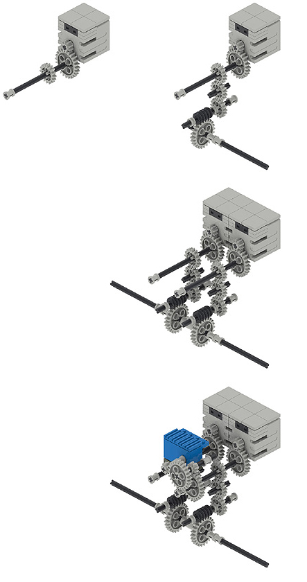
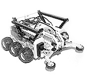
| ‘Skid
Steer’ Drive Assembly for the M.O.P Chassis. Mechanically
linked motors drive an Adder / Subtractor gear assembly. Angle
sensors are mounted off each drive axel to monitor both axle
rotations.
|
| |
|
| |
|
While making the gear train more complex it negates any issues
of motor variance and produces very reliable and consistent performance.
Again specific gearing on each motor can control the speed, or
accuracy of either forward/Reverse, or left/right movement. Rotation
sensors built into the Drive Gearing allow us to monitor either
motor or drive axle rotations.
|
| |
|
 |
| |
|
|
| |
|
Speed and Mechanical
Accuracy
As we know the M.O.P chassis is capable of supporting
many different gearing configurations within its drive assembly.
The three physical
attributes of the M.O.P which determine operational speed are,
Drive Gearing ratio, motor speed (RPM), and wheel size (Diameter).
By modifying any, or all three of these has an effect on the Rover’s
overall operational speed. The real art is knowing which attribute
to change, and what impact this will have on the other two. The
M.O.P chassis allows you to experiment with all three without having
to re-engineer the entire Rover.
Operating a slow moving Rover is a piece of cake. It takes a while
to get where it is going allowing you (the operator, or it’s
own electronic brain) time to adjust, and compensate to keep
it on track.. However as the Rover’s operating speed increases
your available reaction time decreases. You have to make decisions
and adjustments quicker, and more accurately because your Rover
is moving so much faster. Operational tolerances have to be drastically
reduced as speed increases.
In order to control Rover movement and orientation remotely we
need the Rover’s drive assembly to deliver us information
about motor and wheel rotation and position – This is often
referred to as the drive assembly’s ‘Mechanical Accuracy’ or ‘Rotation
density’. The greater the operational speed of the Rover,
the greater Mechanical Accuracy required of it Drive assembly.
This allows for more accurate (and predictable) navigation algorithms
to be implemented while minimizing accumulative error associated
with this type of navigation processing.
(We are talking mechanical control
characteristics as apposed to software controlled characteristics.
How the drive assembly
physically integrates with control and navigation sensors).
The key to determining how much Mechanical accuracy your drive
assembly needs is to look at the relationship between Motor, drive
gearing, Wheel diameter, and sensor revolutions.
|
| |
|
 Consider a motor with a 24:1 gear ratio driving an 82mm diameter
wheel. The motor will turn 24 times for each wheel revolution,
moving the Rover 82mm. If you attach a Rotation sensor to the wheel
axle you have a rotation density of 16:1 (16x1) units per wheel
revolution. Physically this translates to 5.125mm of movement to
1 rotation unit. However if you attach the Rotation sensor to the
Motor’s axle (before the gearing reduction) you get a 2400%
increase in rotation density to 384:1 (16x24) per wheel revolution.
In real terms this yields an increase in control accuracy from
5.125mm (82/16) to 0.213mm per rotation unit. Consider a motor with a 24:1 gear ratio driving an 82mm diameter
wheel. The motor will turn 24 times for each wheel revolution,
moving the Rover 82mm. If you attach a Rotation sensor to the wheel
axle you have a rotation density of 16:1 (16x1) units per wheel
revolution. Physically this translates to 5.125mm of movement to
1 rotation unit. However if you attach the Rotation sensor to the
Motor’s axle (before the gearing reduction) you get a 2400%
increase in rotation density to 384:1 (16x24) per wheel revolution.
In real terms this yields an increase in control accuracy from
5.125mm (82/16) to 0.213mm per rotation unit.
The point to remember here is that by altering the gear ratio
between the motor and Rotation sensor we can dramatically increase
the relative accuracy of the Rotation sensors output – or
increase the Mechanical Accuracy of the drive assembly without
affecting the gearing relationship between the motor and wheels.
Both Drive Gearing configurations within the M.O.P (Exclusive
and Differential) use LEGO Rotation Sensors to obtain axle rotation
information relative to wheel rotations. Both Drive assembly configurations
have a high
Mechanical Accuracy. In both instances the Rotation sensor is geared
3:1 in relation to the Motor. However the Exclusive Drive configuration
has a Sensor to Wheel revolution ratio of 216:1 and in the case
of the Differential Drive configuration a whopping 864:1 !!! Talk
about splitting hairs
|
| |
|
 |
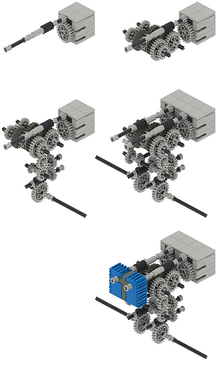
Both
Drive Gearing configurations within the M.O.P (Exclusive and
Differential)
use Rotation Sensors to obtain axle rotation information relative
to wheel rotations.
The fist column illustrates the drive gearing to the wheels,
while the second column shows the gearing to the Rotation Sensor
(this is where Rotation Density comes into play). The top
row illustrates this relationship to an Exclusive skid
steering implementation, and the bottom row to a Differential
skid steering implementation.
Coloured gears indicate a change in gear ratio within the
drive assembly.
|
| |
|
|
|
|
|
|
 |
| ALL TERRAIN DOZER |
|
Martyn Boogaarts was asked by LEGO (Netherlands) to a design a
Rover for demonstration at the inaugural Dutch FLL challenge.
Over four hours Martyn designed the Modular-All-Terrain-Rover.
He says, ” I wanted to show that it is possible
to create a robot that can compete in all the tasks
and still stays fully within the limitations of the
game”
The All-Terrain-Dozer has a common chassis with ‘plug-n-play’ attachments
which are specifically suited to each of the mission
objectives within the FLL competition.

More images and information about Martyn’s All – Terrain
Dozer can be found here.
FLL ‘Mission Mars’ contest information
can be found here.
|
|
|
 |
|
 |
|
| |
|
| ADDERS
AND SUBTRACTORS |
|
Adder, Subtractor, what the difference?. No, its not a calculation
machine as you know it, but it’s
more familiar than you would think.
A differential, or Adder / Subtractor gear train gets its
name form the fact that it can ‘add’ or ‘subtract’ the
output of each drive shaft. Depending on the configuration
you are able to negate the product of one output with that
of another producing a difference.
Many different Adder / Subtractor and differential gearing
combos have been developed and LUGNET Technic’s discussion
group has a fabulous resource on the subject found here.
|
|
|
|
|
|
|
| |
|
| ROTATION
SENSORS |
|
| The LEGO Rotation (Angle) Sensor as the name suggests detects
rotations. Its body has a hole that easily fits a LEGO axle.
When connected to the RCX, this sensor counts a single unit for
every 16th of a turn the axle makes, (16 units per full rotation).
This gives us an accuracy of 22.5 degrees per unit (16 units
making 360 degrees).
By counting rotations, and combining them with Drive Ratio,
wheel diameter and track you are able to calculate orientation,
drive direction and total distance traveled. In fact all of the
telemetry needed for basic navigation can come from a single
Rotation sensor.
However the Rotation sensor can become troublesome when used
in some applications.
Philippe Hurbain pulled apart his Rotation Sensor to find out
why.
And Steve Baker determined the best operational
speeds at which
to
poll the sensor,
Unless you want to modify your sensor like Philo, try to stick
to axle rotation rates around 50 to 300rpm and the Rotation sensor
will not drop any counts. You can drive the sensor directly from
the LEGO 9V Geared Technic motor - and you can run it 5x slower
than that and still not lose counts. However, don't run 25x slower
or 5x faster than the motor or you will lose counts. Rotation
axle speeds less than 12 rpm or greater than 1400 rpm are definitely
bad news if you need accurate readings
|
|
|
|
|
|
|
| |
|
| FINDING
WHEEL RPM |
|
|
To find the Revolutions per Minute (RPM) of the Rovers
wheels (r) we need to know the Following things.
Motor RPM: The RPM of a typical LEGO Geared 9V Technic
motor under normal operating load sits at about 220 RPM.
Drive Ratio: The ratio between motor RPM and Drive axle
RPM. We can figure this out by calculating the Gearing
ratio of the Drive train.
 Example Example
A Geared 9V Technic Motor with an 8t gear is driving
a 24t gear (3:1) which is linked (1:1) to a Worm gear
which is intern driving the final output axle through
a 24t gear (24:1). The gear ratio looks like this:
3:1 x 1:1 x24:1 or 72:1
For every 72 turns of the motor, the drive axle turns
once.
Motor Speed = 220 rpm
Drive Ratio = 72
then
Wheel RPM = 220/72 or 3.05
|
|
|
|
|
|
|
| |
|
| FINDING
OPERATING SPEED |
|
|
To calculate
the rovers operating speed we only need multiply the
Wheels RPM with its diameter.
If our Rover Wheel has a diameter of 82mm then we can
work out our Rover’s operating speed.
We can use the following equations:
Gearing Ratio = 72:1
d = 82mm
r = 3.05
PI = 3.142 To find Kilometers
per hour
kph = (PIdr)60/1,000,000
kph = (3.142 x 82 x 3.05)60/1,000,000
= 0.047 kilometers per hour
To find meters per minute
mpm = (PIdr) /1,000
mpm = (3.142 x 82 x 3.05)/1,000
= 0.788 meters a minute
To find centimeters per second
cps = (PIdr) /600
cps = (3.142 x 82 x 3.05)/600
= 1.31 centimeters a second
|
|
|
|
|
|
|
| |
|
| FINDING
ROTATION DENSITY |
|
|
Mechanical accuracy is a measure of the drive train’s
ability to supply a sufficient axle rotation ‘density’ to
control sensors. Rotation density is the ratio between
Rotation Sensor Axle rotation and Wheel Axle Rotation.
To find the Rotation Density of a specific axle within
a drive Gearing assembly we need to identify the ratio
between Wheel RPM and the RPM of the axle on which the
rotation sensor is mounted.
The two illustrated examples (bottom of the page) have
the following Rotation Density ratios:
Exclusive Drive Gearing
(Sensor rotations per wheel revolution)
Motor = 72
Rotation Sensor = 216
Wheel = 1
Rotation Density = 216:1
3456 units (216x16) per wheel revolution
Differential Drive Gearing
(Sensor rotations per wheel revolution)
Motor = 288
Rotation Sensor = 864
Wheel = 1
Rotation Density = 864:1
13824 units (864 x 16) per wheel revolution |
|
|
|
|
|
|
| |
| |
| |
|