|
 Example
1 Example
1
To calculate the top speed of a Rover whose's
drive train consists of a Geared 9V Technic
Motor directly
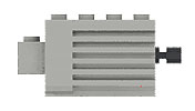
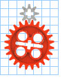
driving (1:1) a Worm gear connected to a 24t
gear. The output of the 24t gear is directly
connected
(1:1) to a Technic Motorcycle wheel and tyre
combo. What would be the estimated top speed
of this
Rover?
Gearing Ratio = 24:1
d = 82mm
r = 9.167 RPM
PI = 3.142
kph = (3.142 x 82 x 9.167)60/1,000,000
= 0.142 kilometers per
hour
mpm = (3.142 x 82 x 9.167)/1,000
= 2.361 meters a minute
mps = (3.142 x 82 x 9.167)/60,000
= 0.039 meters a second
 Example
2 Example
2
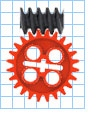
As above, except our Motor is driving an 8t gear
instead of a Worm gear. Lets assume the wheel
does
not change.What would be the new estimated top
speed?
Gearing Ratio = 3:1
d = 82mm
r = 73.333 RPM
PI = 3.142
kph = (3.142 x 82 x 73.333)60/1,000,000
= 1.134 kilometers per hour
mpm = (3.142 x 82 x 73.333)/1,000
= 18.893 meters a minute
mps = (3.142 x 82 x 73.333)/60,000
= 0.315 meters a second
|


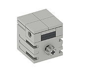
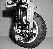
 The
second component of the Wheel Assembly we will focus on is wheel
motivation- How each wheel is powered and driven. Typically each
wheel on a Rover is powered - whether mechanically coupled to another
wheel (as is the case with the Rocky 7 Rover) or individually driven
by its own dedicated motor. Independently driven wheels are difficult
to implement in LEGO® . Their design, like always, involves a trade-off
between functionality and performance. The two competing issues
are:
The
second component of the Wheel Assembly we will focus on is wheel
motivation- How each wheel is powered and driven. Typically each
wheel on a Rover is powered - whether mechanically coupled to another
wheel (as is the case with the Rocky 7 Rover) or individually driven
by its own dedicated motor. Independently driven wheels are difficult
to implement in LEGO® . Their design, like always, involves a trade-off
between functionality and performance. The two competing issues
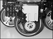
are: 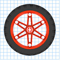 A
typical LEGO® 9V Geared motor spins at approximately 220 revolutions
a minute (RPM) under typical load (see sidebar). A drive train
might reduce this by 24. The motor turns 24 times for every 1
revolution
of the output axle. (This ratio is described as 24:1. Incidentally
this is a common gearing reduction available in LEGO® as it is
the
product of Worm gear driving a 24t gear).
A
typical LEGO® 9V Geared motor spins at approximately 220 revolutions
a minute (RPM) under typical load (see sidebar). A drive train
might reduce this by 24. The motor turns 24 times for every 1
revolution
of the output axle. (This ratio is described as 24:1. Incidentally
this is a common gearing reduction available in LEGO® as it is
the
product of Worm gear driving a 24t gear). 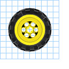 The
wheel’s diameter acts as the final gearing of your drive train.
Small wheels have a smaller circumference. They travel less distance
per revolution, than larger wheels. By changing to a smaller wheel
in the above example, Say a small Technic balloon tyre (43mm diameter)
our 24:1 gear train yields a top speed of 1.239mpm (about a 47%
reduction) and our 3:1 gear train, a top speed of 9.908mpm. However
the torque generated by both (the climbing power) has increased
reciprocally by about 47%.
The
wheel’s diameter acts as the final gearing of your drive train.
Small wheels have a smaller circumference. They travel less distance
per revolution, than larger wheels. By changing to a smaller wheel
in the above example, Say a small Technic balloon tyre (43mm diameter)
our 24:1 gear train yields a top speed of 1.239mpm (about a 47%
reduction) and our 3:1 gear train, a top speed of 9.908mpm. However
the torque generated by both (the climbing power) has increased
reciprocally by about 47%.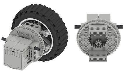
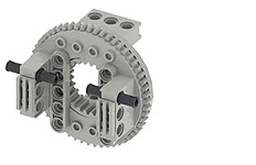
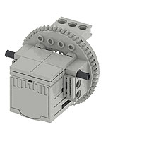
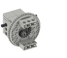
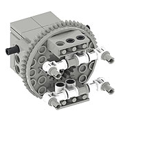
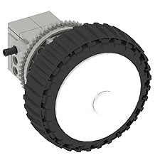
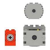
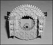
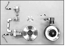
 Brian
Sad’s powered turntable design was the starting point for
the YogiCub’s direct drive hubs. Direct drive proved to
be more economical than the traditional method of supplying drive
via an
axle. It is mechanically strong used less parts, gears, linkages,
axles etc..
Brian
Sad’s powered turntable design was the starting point for
the YogiCub’s direct drive hubs. Direct drive proved to
be more economical than the traditional method of supplying drive
via an
axle. It is mechanically strong used less parts, gears, linkages,
axles etc..