|
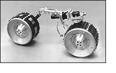
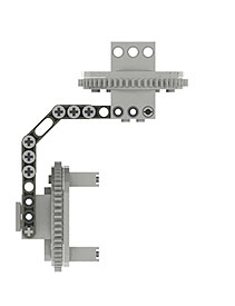
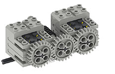
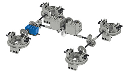
YogiCub has a common mechanical linkage which turns
all pivoting wheel assemblies.
This is driven by 2x mechanically linked 9V geared
motors. The final gearing at the turntables is 56:1
(1 rotation for every 56 of the motor). This is figured
out by the following:
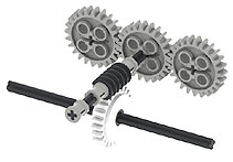
Motor driving Worm gear
1:1
Worm gear driving a 24t Clutch gear
24:1
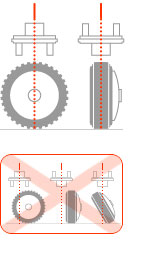
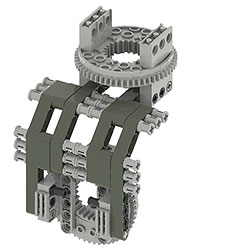
24t Crown gear driving a 56t turntable outer ring.
7:3
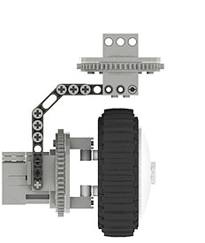
Overall gearing
168:3 or 56:1
RPM at Turntable
(assuming 220RMP at motor)
~ 3.929 RPM
Estimated time to travel 45°
= 1.91 sec
Total ° traveled in 60 seconds
1,414.29° = 3.929
x 360
Total ° traveled in 1 second
23.57 ° = 1,414.29/
60
Time taken to travel 45°
1.91 = 1/23.57 x 45
|